Design and Implementation of IoT and Non-IoT Modules for Smart Factory
Copyright ⓒ 2018 The Digital Contents Society
This is an Open Access article distributed under the terms of the Creative Commons Attribution Non-CommercialLicense(http://creativecommons.org/licenses/by-nc/3.0/) which permits unrestricted non-commercial use, distribution, and reproduction in any medium, provided the original work is properly cited.

Abstract
As senser network technology or Internet of Things developed, machines for processes used in factories are gradually being replaced with sensors and actuators equipped with Internet of Things technology, but as they cannot replace existing non-IoT machines in terms of costs, there are many issues. This paper proposes a system that can be efficiently monitored and managed through highly accessible media (smart phone, PC, etc.) for processes in operation that can be operated simultaneously by linking IoT devices to non-IoT devices. The system presented in this paper consists of a sensor network in single-board computer (SBC) medium for IoT modules, and in case of non-IoT, the PLC(Programmable Logic Controller) was equipped with an Ethernet interface of IEEE 802.3 for communication.
초록
융복합 시대가 도래하면서 센서 네트워크나 사물인터넷 기술이 매우 빠른 속도로 발전하고 있다. 이로 인하여 공장에서 사용되는 공정용 센서나 기기들은 사물인터넷 기술이 탑재된 방식으로 대체되고 있으나 비용 등 여러 가지 측면에서 기존 공장에서 사용되는 비 IoT 기계를 대체할 수 없다는 단점이 있다. 이에 본 논문에서는 IoT 장치와 비 IoT 장치를 연동하여 동시에 스마트 팩토리를 관리할 수 있고 가동 중인 공정에 대하여 사용자는 접근성이 높은 매체(스마트폰, PC 등)를 통해 효율적으로 모니터링하고 관리 가능한 시스템을 제안한다. 제안된 시스템은 IoT 모듈의 경우 단일보드 컴퓨터(Single-board Computer) 매체에서 센서 네트워크를 구성하며, 비 IoT의 경우 PLC(Programmable Logic Controller)에 IEEE 802.3의 이더넷 인터페이스를 장착하여 통신이 가능하도록 하여 데이터 통신을 수행하였다.
Keywords:
Smart factory, Internet of Things, Single-board Computer, PLC키워드:
스마트 팩토리, 사물인터넷, 단일보드컴퓨터, PLCⅠ. INTRODUCTION
Programable Logic Controller (PLC) is mainly responsible for both process lines and production at the existing system's production site. In order to expand the scale of the automation process using PLC and to have an organic change of the production type, it was necessary to additionally purchase PLC or to expand the input / output, and to cope with the large cost[1]. However, as the sensor network technology began to evolve, the stability and performance of sensors and actuators using the Internet were secured. However, as the sensor network technology started to evolve, the stability and performance of sensors and actuators using the Internet were secured. As a result, automation control at the production site was replaced by the Internet of Things, not the PLC[2]. However, The larger the scale, the greater the cost burden for changes in the production method.
Therefore, the management system proposed in this paper is designed to reduce the additional cost by linking the Internet of things and the non-IoT module, and to reuse existing system. In addition, a monitoring and management system is additionally installed so that both the administrator and the user can easily grasp and manipulate the production process.
Ⅱ. DESIGN OF MANAGEMENT SYSTEMS
2-1 System structure
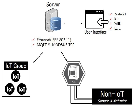
The management system has the following structure. A gateway server is installed to control and monitor the values of the devices in the smart factory, and a communication-enabled PLC with an Ethernet interface, which is linked with the existing non-IoT module, And a plurality of communicable SBCs connected by WiFi to which a sensor or an actuator is attached. Also, it is possible to create and access a compatible web-type application in the administrator's media (smart phone, PC, etc.) so that the processed information from the gateway server can be easily operated by the administrator or the user. Through this structure, the user can easily manage and control the process data through the gateway server. Figure 1 shows the structure of the system described above.
2-2 MQTT protocol
The MQTT protocol is used when communicating with the SBC, the Internet module of objects. Message Queuing Telemetry Transport (MQTT) is a lightweight publish / subscribe messaging protocol that is designed to be used at low power and low bandwidth for use in machin-to-machin(M2M)[3].
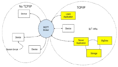
MQTT is advantageous in that it can be operated on a low power, unreliable network, and no TCP / IP base as described above. Especially, it is attracting much attention in the field of Internet of things because it is advantageous for control of small devices and collection of sensor information[4].
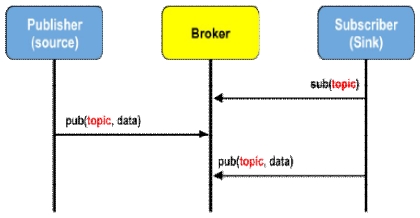
The basic principle of this protocol is to publish a message as shown in Figure 3 and subscribe to a topic of interest.
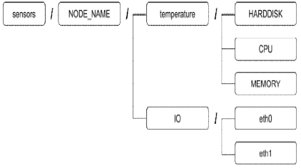
Both the Publisher and the Subscriber act as clients to the Broker. A publisher connects to a relay server for the purpose of subscribing to a topic for the purpose of publishing a topic. One or more publications and subscriptions can connect to an broker to issue or subscribe to a topic. Multiple clients can also subscribe to a single topic. Subjects can be hierarchically structured using slashes (/) to enable efficient management of many unspecified sensor devices. For example, if you have a sensor that measures the state of your computer as shown in Figure 4 below, you could configure it as follows.
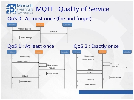
There is also a Quality of Service (QoS) level in the protocol to ensure quality of service. This indicates the reliability of the message. There is a difference in the message delivery method according to each level. Unlike the TCP / IP environment, packets can be corrupted. By setting the QoS level and acting according to each level, reliability of message delivery is assured. Figure 5 shows the message delivery method for each QoS level.
In this system, communication with the SBC was performed using the QoS 0 level. In case of PLC, since the sensor of PLC is managed by gateway server using TCP / IP protocol called MODBUS TCP, TCP / IP and No-TCP / IP are mixed on the local network and reliability of MQTT communication is ensured for control stability. Therefore, we set QoS level to 0 and processed QoS directly in software.
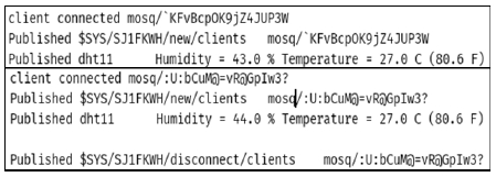
After that, we tested communication of the sensed data with the gateway server and successfully read and control the data from the sensor directly from the SBC through the server.
2-3 MODBUS-TCP protocol
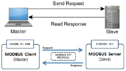
Modbus TCP is a communication protocol that is often used in the field of industrial fieldbus. It is a communication method designed for interfacing between a parent device and a child device over a TCP / IP network. In this paper, we use it for communication between PLC and server. Figure 6 shows the structure of the corresponding communication method.
The communication standard of Modbus TCP is divided into roles of a master (client) and a slave (server)[4]. The slave responds to the data requested by the master and is in a passive position to perform only the requested operation. On the other hand, the master side must actively handle slave devices such as reading desired data or writing desired data.
In this system, PLC was configured as slave and gateway server as master. The temperature and humidity sensor attached to the PLC interface was directly obtained through the gateway server and acquired through the MODBUS command, and the server managed and controlled the sensed data.
The reason for using the Modbus TCP protocol is obviously the low cost and versatility of standard Ethernet. If only the TCP / IP sockets were understandable, it would take less to configure the operating system in just a few hours to set up PC communications. In addition, due to the versatility of Ethernet, it was possible to proceed using standard open protocols without having to configure expensive communication separately.
2-4 Interworking gateway server between PLC and SBC module
The sensor connections of SBC and PLC to be linked with the management system proceed as shown in Table 1 below.
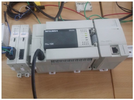
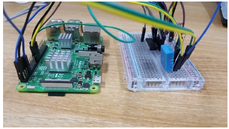
PLC and SBC were used to monitor and store the sensed data. In the PLC, only the temperature sensor and the Ethernet interface are attached as shown in Fig. 7, so that information sensing and communication through the Modbus TCP are possible. In the case of SBC, as shown in Fig. 8, a breadboard is connected to the direct input / output, and a sensor is connected to collect the information, and a converter for converting the value to a digital data value is constructed. After completing the input / output configuration of all the modules, a number of tests were conducted. As a result, both modules completed communication as shown in Fig. 9.
After the integration, in order to directly monitor and manage the sensor data collected from the gateway server, configure the Web client was the figure is shown in Figure 10.
Ⅲ. CONCLUSION
In this paper, we propose a sensor network environment through MQTT communication by attaching sensor to SBC and PLC which can perform TCP / IP communication with IEEE 802.3 Ethernet interface module for design and implementation of interworking and management system between IoT and non-IoT module. In the overall system configuration, the data of each sensor is collected from each object Internet and non-IoT module by moving the temperature and humidity sensor, and the data is stored in the gateway server and processed by the user so that the user can directly check the web. The purpose of this paper is to propose a system structure that can be configured more cheaply and easily in the existing environment of non-IoT process. In order to verify the system, sensor data generation, collection, and manipulation between the modules were performed to realize the actual system construction situation. In the future, we will analyze the performance of the development system directly from the target workplace.
Acknowledgments
This work (Grants No. S2598811 ) was supported by project for Cooperative R&D between Industry, Academy, and Research Institute funded Korea Ministry of SMEs and Startups in 2018.
References
- S. I. Jeong, I. G. Chun, "Implementation of Low-Cost Data Management System for Smart factory", Department of Information and Communication Technology, 18(6), p670-671, June), (2018.
- S. G. Cha, "Trends in Smart Factory Standardization with IoT/M2M System structure", Information and Communication Magazine, 32(5), p36-41, April), (2015.
- Wikipedia - The Free Encyclopedia, “MQTT”, Available: https://en.wikipedia.org/wiki/MQTT.
- S. I. Na, H. J. Kim, "Design of Anomaly Detection System Based on Big Data in Internet of Things", Journal of Digital Contents Society(JDCS), 19(2), p377-383, February.), (2018.
- Comfile Technology’s Document Library, “What is MODBUS-TCP”, Available: http://comfilewiki.co.kr/ko/doku.php?id=tcpport:modbus-tcp_%ED%94%84%EB%A1%9C%ED%86%A0%EC%BD%9C%EC%9D%B4%EB%9E%80:index.
저자소개

2013 ~ Present: Attended Computer Engineering Department, Hanbat National University

1980: Department of Electronic Engineering, Kyungpook National University(Bachelor of Engineering)
1983: Department of Electronic Engineering, Kyungpook National University(Master of Engineering)
1994: Department of Computer Engineering, Dankook University(Doctor of Engineering)
1983-1996: Korea Electronics and Telecommunications Research Institute(General manager)
1989: Professional Engineer Information Processing
1996 ~ Present: Professor of Computer Engineering, Hanbat National University
※ Field of interest: data communication, information protection, visualization of data, etc.

1997: Department of Electronics Engineering, Hannam University()
2013: Department of Defense Acquisition · M&S, Hannam University School of Defense Strategy (Master of Engineering)
2018: Department of Military Science and Information, Kongju National University (Doctor of Engineering)
1998 ~ 2002: Senior Researcher, C & C, Military Mutual Aid Association
2003 ~ 2017: Director of M & D Information Technology / ARES Development Department
2017 ~ Current: Utobiz Co., Ltd. Representative Director
※ Field of interest: Defense M & S, data linkage, war games, virtual reality, augmented reality, etc.

2007: Graduate School of Visual Arts, Kongju National University (Master of Engineering)
2016: Pusan University of Foreign Studies Graduate School (Doctor of Engineering - ICT Creativity Fusion)
2012 - 2017: IH Tech Director
2017 ~ Current: Utobiz Co., Ltd. Director
※ Field of interest: HCI, Bigdata, ICT, Virtual Reality, Augmented Reality, Interactive, etc.
