무인기 제동장치 제어기의 온도 및 유동해석
Copyright ⓒ 2018 The Digital Contents Society
This is an Open Access article distributed under the terms of the Creative Commons Attribution Non-CommercialLicense(http://creativecommons.org/licenses/by-nc/3.0/) which permits unrestricted non-commercial use, distribution, and reproduction in any medium, provided the original work is properly cited.

초록
본 논문은 기계, 항공, 군사분야 등에서 널리 사용될 수 있는 무인기 제동장치 제어기 내부의 칩들이나 보드들에 대한 온도와 유동해석을 다룬다. 이러한 무인 제동장치 제어기는 정밀한 작동이 이루어져야 되기 때문에 신뢰성 확보가 매우 중요하다. 제동장치 제어기가 사용되는 일반적인 주위의 환경 온도는 약 -25oC-50oC(248oK-323oK)이다. 제동장치 제어기가 신뢰성을 갖추기 위해 중요시 되는 것은 제동장치 제어기 내의 열 발생이 어느 한계 수준(-25oC-95oC(248oK-358oK)내로 유지되어야 한다. 따라서 제동장치 제어기 내의 온도 및 유동 특성에 대한 연구가 필요하게 된다. 본 논문의 수치 시뮬레이션을 위해 상용 소프트웨어인 Solid-Works Flow Simulation을 사용하였다. 본 논문의 목적은 내부의 칩들과 보드들을 지니는 제동장치 제어기의 온도 및 유동특성을 해석하여 제동장치 제어기의 안전한 설계를 하는데 있다.
Abstract
This paper deals with the temperature and fluid analysis for chips and boards of brake control units of an unmanned aerial vehicle which is widely used in the fields of machinery, aerospace and military fields. It is important to ensure reliability of such brake control units since its operation should be kept with a precision work. The temperature of the environment where the brake controller units are used is about -25oC-50oC(248oK-323oK). Heat generated in the brake control units should be maintained within certain threshold levels,(-25oC-95oC(248oK-368oK) to ensure reliability. Therefore, the study of the temperature and flow characteristics in the brake control units is required. In the paper, commercial software Solid-Works Flow Simulation was used for the numerical simulations. The purpose of the study is to design the brake control units safely analyzing the temperature and flow characteristics inside of the brake control units composed of chips and boards.
Keywords:
Temperature and flow analysis, Temperature distribution, Brake control units, Unmanned aerial vehicle, Numerical simulation키워드:
온도 및 유동 해석, 온도 분포, 제동 장치 제어기, 무인 항공기, 수치 시뮬레이션I. 서 론
무인기 제동장치 제어기는 기계공학, 항공공학, 군사 분야 등에서 널리 사용될 수 있는 제어기로서, 제동력이 과다할 경우는 바퀴의 미끄럼이 발생하게 되고, 이러한 미끄럼의 정도는 바퀴의 축에 장착된 휠 속도센서(wheel speed tranceducer)의 출력신호를 바탕으로 제동장치 제어기에서 판단하게 된다.
제동장치 제어기는 미끄럼의 정도에 따라 실시간으로 ABS(Anti-Brake System) 제어밸브에 제어 명령 신호를 전달하게 되므로 이러한 제동장치 제어기의 정밀도가 무인항공기의 안전운항에 미치는 영향은 매우 중요하다.
제동장치 제어기가 사용되는 주위환경의 온도는 약 (248 ∼323)이다. 제동장치 제어기에서 중요시 간주되는 문제 중의 하나는 제어기 내의 열 발생이 어느 한계수준(368) 이하로 유지되어야 정밀도와 신뢰성을 가질 수 있다. 따라서 제동장치 제어기 내부의 온도 및 유동 특성에 대한 연구가 필요하게 된다.
난류 유동에 관한 고찰로서 Jones 등[1]은 여러가지 복잡한 형상의 유동에 저 레이놀즈수 k - ϵ 난류 모델을 이용하여 계산한 수치해석과 실험결과가 잘 일치하고 있음을 연구하였다. 열 및 유동해석에 대한 단순한 연구는 Fusegi 등[2]과 Pallares 등[3]에 의해 이루어졌는데, 이들은 온도가 다른 단순한 수직면이나 수평면을 갖는 3차원 공동(cavity)내에서의 유동 형태와 특성을 수치 해석적으로 연구하였다.
이러한 연구들과 더불어, 제동장치제어기나 전자 및 전기장치의 온도 및 유동 해석에 대한 연구도 이루어져 왔다. Hong 등[4]은 터보펌프 인듀서(inducer)의 성능 및 유동 특성을 연구하였는데, 이들은 인듀서의 1차원 설계 모델과 3차원 유동해석을 통해 효율적인 인듀서의 설계 방안을 제시하였다.
Tsay와 Cheng[5]은 열 발생기 블록에 탑재된 다수의 보드(boards)를 갖는 채널에서의 2차원 대류 문제를 수치해석적으로 연구하였다. Byon 등[6]은 칩(chip)의 최고 온도에 미치는 칩의 두께의 효과에 대한 실험 및 수치해석 연구를 병행하였고, Sharma 등[7]은 수냉 마이크로 프로세서 칩의 최적 온도 작동에 관한 연구를 하였다.
Kim 등[8]은 몰드 변압기의 구조 영역별 온도분포 및 최고 온도(hot spot temperature)를 예측하고, 변압기의 3차원 열 유동해석을 상용 소프트웨어인 FLUENT를 이용하여 수행하였다.
그 후, Jun과 Kim[9], Jeong과 Kim[10], Choi와 Shin[11]은 다양한 대상 모델에 대해, 열해석 모델의 간략화 방법이나 새로운 수치 해석적 기법을 개발하여 연구하였다.
최근 Ryu 등[12]은 구동제어기의 열 유동 해석에 관한 수치 해석 연구를 하였다.
본 논문에서는 제동장치 제어기와 제어기 내부의 각종 칩들과 보드들을 3차원 모델링하고, 이 모델에 대한 온도 및 열 유동해석을 통해, 신뢰성있는 제동장치 제어기를 설계하는데 있다.
II. 본 론
2-1 해석 모델
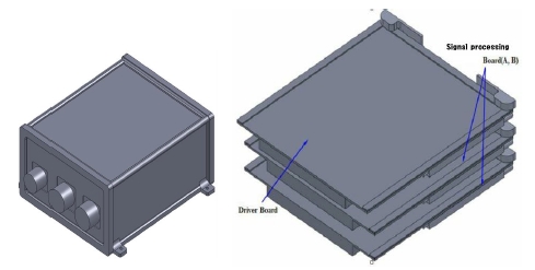
제동장치 제어기와 제어기 내의 각종 보드들의 3차원 모델은 Fig. 1에 나타난 바와 같다.
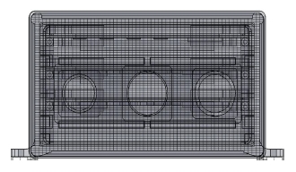
Fig. 2는 온도 및 유동 해석을 위한 제동장치 제어기의 내부 유체격자 및 고체격자들의 단면을 보여주고 있고, Table 1은 유체격자, 고체격자 등 Fig. 2에 도시된 격자 모델의 종류와 격자 수를 나타낸다. 또한, Table 1에서 irregular cell은 Fig. 2의 유체 및 고체격자를 생성하는 과정에 있어, 불규칙한 격자의 생성을 나타내는데 본 논문에서는 나타나지 않았다.
2-2 지배방정식과 경계조건
본 논문에서 지배방정식은 식 (1)-(3)으로 나타내지는 연속방정식, 운동량 방정식, 난류 운동에너지 방정식과 식 (4)-(5)로 표현되는 난류 운동에너지 소산율 방정식 등으로 표현된다. 또한, 난류 모델로서 표준 모델을 사용하였다. 한편, 경계조건은 외부 초기 온도를 고온의 경우 43oC (316oK), 저온일 경우 -66oC(207oK)로 입력하였고, 또한, 외벽과 외부의 공기의 열전달계수는 h = 5(W/m2oK)로 가정하였다.
| (1) |
| (2) |
| (3) |
식 (3)에서, 이다.
| (4) |
| (5) |
식 (1)-(5)에서, ρ는 밀도, ui는 속도성분, τij는 점성 전단 응력 텐서, 는 Reynolds 응력 텐서, k는 난류운동에너지, ϵ는 소산율, H는 엔탈피를 나타낸다. 또한, 는 시간 미분연산자, 는 위치 미분연산자를 나타내며, h는 열전달계수를 나타낸다.
본 논문에서는 팬(fan) 등과 같이 외부와 내부 사이에 강제적인 유동을 유발하는 인자가 없으므로, 가열과정에 의하여 생기는 유체의 밀도변화 때문에 일어나는 유동현상인 자연대류 열전달을 고려하기 위하여 자연대류를 일으키는 부력으로 중력을 택하였으며, 유동장은 정상 상태의 층류와 난류 유동으로 가정하였다.
2-3 수치 해석결과 및 검토
본 논문에서는 모델링에 있어서 SolidWorks 2015를 사용하였으며, 온도 및 유동 해석으로는 SolidWorks Flow Simulation 2015를 사용하였다. Table 2는 본 논문의 해석에 사용된 제동장치 제어기의 구성요소에 대한 재질과 물성치를 보여주고, Table 3은 각각의 부품에 대한 발열량을 나타낸다.
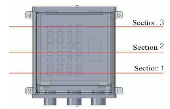
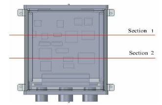
Fig. 3은 온도해석을 위한 드라이버 보드의 각 단면의 위치를 나타낸다.
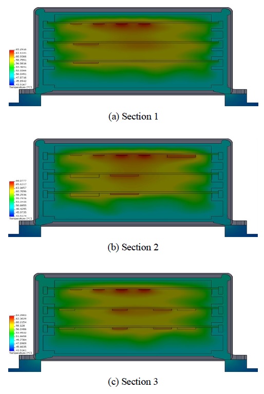
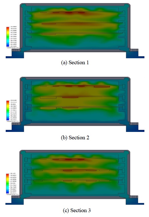
Fig. 4와 Fig. 5는 드라이버 보드의 각 단면에서, 각각 고온의 경우와 저온의 경우에 있어서의 온도 분포를 나타낸다. 고온의 경우 단면 1부터 단면 3까지 최고 온도는 각각 65.29oC, 68.07oC, 64.39oC를 나타내었고, 저온에서는 각각 -34.99oC, -29.61oC, -36.09oC를 나타내고 있다.
Fig. 6은 온도해석을 위한 신호처리 보드의 각 단면의 위치를 나타낸다.
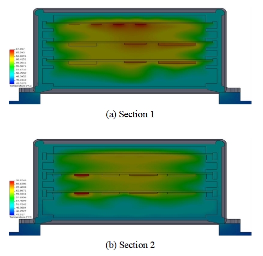
Fig. 7은 신호처리 보드의 각 단면에서, 고온의 경우에 있어서의 온도 분포를 나타낸다. 고온의 경우 단면 1부터 단면 2까지 최고 온도는 각각 67.66oC, 70.87oC를 나타내었다. 저온의 경우는 그림으로 나타내지는 않았지만, 각 단면에서 각각 -30.36oC, -27.49oC를 나타내었다.
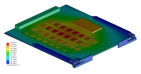
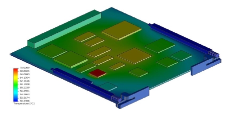
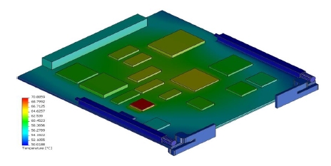
Fig. 8에서 Fig. 10은 고온에서, 드라이버 보드와 신호처리 보드 A와 B의 각 표면에서의 온도 분포를 나타낸다. 최고 온도는 각각 68. 08oC, 70.04oC, 70.89oC를 나타내고 있다. 저온의 경우는 그림으로 나타내지는 않지만, 드라이버 보드와 신호처리 보드 A와 B의 각 표면에서의 온도 분포는 각각 -29.62oC, -27.47oC, -27.97oC를 나타내 보였다.
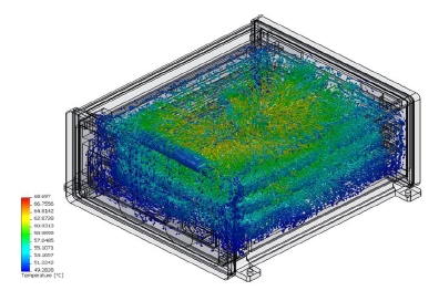
Fig. 11은 고온에서의 제동장치 제어기 내부의 온도와 유동분포를 나타낸다.
III. 결 론
제동장치 제어기의 온도 및 열 유동해석을 통해 다음과 같은 결론을 얻었다.
제동장치 제어기 내부 온도 분포는 고온의 경우, 한계온도인 95oC 이상의 온도는 모든 부품에서 발생되지 않았으며, 저온의 경우, 대부분의 칩(chip) 부품에서 -30oC 안팎의 온도 분포를 보이고 있어 비교적 안전한 상태라고 보여진다. 또한, 드라이버 보드나 신호처리 보드에 부착되는 알루미늄 판을 더 크게 하여 열 방출 효과를 증대시키는 방안이 요구된다.
References
-
W. P. Jones, and B. E. Launder, “The Calculation of Low-Reynolds-number Phenomena with a Two-equation Model of Turbulence”, International Journal of Heat and Mass Transfer, 16, p1119-1130, (1973).
[https://doi.org/10.1016/0017-9310(73)90125-7]

-
T. Fusegi, J. M. Hyun, K. Kuwahara, and B. Farouk, “A Numerical Study of Three-Dimensional Natural Convection in a Differentially Heated Cubical Enclosure”, International Journal of Heat and Mass Transfer, 34(6), p1543-1557, (1991).
[https://doi.org/10.1016/0017-9310(91)90295-p]

- J. Pallares, I. Cuesta, F. X. Grau, and G. Francesc, “Natural Convection in a Cubical Cavity Heated from Below at Low RayLeigh Numbers”, International Journal of Heat and Mass Transfer, 39(15), p3233-3247, (1996).
- S. S. Hong, H. C. Koo, B. J. Cha, and J. H. Kim, “Characteristics of Exit Flow and Performance of a Turbopump Inducer”, Journal of Fluid Machinery, 4(4), p38-44, (2003).
-
Y. L. Tsay, and J. C. Cheng, “Analysis of Convective Heat Transfer Characteristics for a Channel Containing Short Multi-Boards mounted with Heat Generating Blocks”, International Journal of Heat and Mass Transfer, 51, p145-154, (2008).
[https://doi.org/10.1016/j.ijheatmasstransfer.2007.04.006]

-
C. B. Byon, K. S. Choo, and S. J. Kim, “Experimental and Analytical Study on Chip Hot Spot Temperature”, International Journal of Heat and Mass Transfer, 54, p2066-2072, (2011).
[https://doi.org/10.1016/j.ijheatmasstransfer.2010.12.022]

-
C. S. Sharma, S. Zimmermann, M. K. Tiwari, B. Michael, and D. Poulikakos, “Optimal Thermal Operation of Liquid-Cooled Electronic Chips”, International Journal of Heat and Mass Transfer, 55, p1957-1969, (2012).
[https://doi.org/10.1016/j.ijheatmasstransfer.2011.11.052]

-
J. H. Kim, J. G. Lee, K. S. Lee, W. Rhee, and H. B. Lee, “Thermal Fluid Flow Analysis for Temperature Characterization of Mold Transformer in Distribution Power System”, The Transactions of the Korean Institute of Electrical Engineers, 62(1), p6-11, (2013).
[https://doi.org/10.5370/kieep.2013.62.1.006]

-
H. Y. Jun, and J. H. Kim, “A Study on Thermal Model Reduction and Dynamic Response”, Journal of Computational Fluids Engineering, 19(4), p37-44, (2014).
[https://doi.org/10.6112/kscfe.2014.19.4.037]

-
H. S Jeong, and K. Y. Kim, “Effects of Fluidic Oscillator Geometry on Performance”, Journal of Computational Fluids Engineering, 21(3), p77-88, (2016).
[https://doi.org/10.6112/kscfe.2016.21.3.077]

- G. Choi, and S. Shin, “Development of Numerical Technique for the Two-Phase Flow Interacting with Moving Body”, Journal of Computational Fluids Engineering, 23(2), p16-22, (2018).
- B. J. Ryu, B. J. Oh, and Y. S. Kim, “Thermal and Flow Analysis of a Driving Controller for Active Destruction Protections”, Journal of the Korea Academia-Industrial Cooperation Society, 18(2), p235-242, (2017).
저자소개

1981년 : 연세대학교 기계공학과 (공학사)
1983년 : 연세대학교 대학원 (공학석사)
1988년 : 연세대학교 대학원 (공학박사)
1989년 ~ 1989년: 삼성종합기술원
1991년 ~ 1992년: 일본 대판부립대학 객원교수
1989년 ~ 현 재: 한밭대학교 기계공학과 교수
※관심분야:구조물 진동해석, 제어, 추력을 받는 보 구조물의 탄성 안정성

2003년 : University of Utah대학원 (공학석사)
2008년 : University of Utah대학원 (공학박사)
2008년 ~ 2009년: University of Utah
2009년 ~ 2009년: 방위사업청
2009년 ~ 2011년: DGIST
2011년 ~ 현 재: 한밭대학교 기계공학과 교수
※관심분야:스마트액추에이터(smart actuator), 모션제어(motion control), 생체모방로봇(bio-inspired robot), 센서융합(sensor fusion) 등

2002년 2월 : 한밭대학교 기계설계공학과 대학원 (석사)
2011년 8월 : 충남대학교 기계설계공학과 대학원(박사)
2007년 3월 ~ 2013년 8월 : 한밭대학교 시간강사
2015년 6월 ~ 2016년 9월 : 아이겐스코프(주)
2016년 10월 ~ 현재 :국방과학연구소 선임기술원
※관심분야:구조 및 진동해석, 구조물 진동/제어

2001년 : 서울대학교 기계항공공학부 (공학사)
2007년 : 서울대학교 기계항공공학부 대학원(공학박사)
2007년 ~ 2009년 : 삼성전자 반도체총괄 책임연구원
2009년 ~ 2012년 : 서강대학교 기계공학과
BK21 연구교수
2012년 ~ 현 재: 한밭대학교 기계공학과 교수
※관심분야:전자기 구동기(electromagnetic actuator), 스마트 구동기(smart actuator) 생체모방로봇(bio-inspired robot), 등
