A Study on Apply of Smart Sensors for Wheelchair Balancing Control
Copyright ⓒ 2018 The Digital Contents Society
This is an Open Access article distributed under the terms of the Creative Commons Attribution Non-CommercialLicense(http://creativecommons.org/licenses/by-nc/3.0/) which permits unrestricted non-commercial use, distribution, and reproduction in any medium, provided the original work is properly cited.

Abstract
Due to un-balancing weight allocation on the wheelchair the existing wheelchair system are faced with the risk of flipping or falling when a wheelchair goes up to a hill . In to order to be safer during riding the wheelchair, in this paper, we proposed a real-time new solution using the integrated Gyro Sensor and Tilt Sensor for controlling the balance. Because the typical property of wheelchair is for the special user who meets the difficulty in moving on foot the maintain the balance of wheel-chair systems have become important and helpful. In our method, we calculate the seat angle using information from Tilt Sensor. However, due to the law of inertia when a wheelchair is moving there is a deviation in the output value of Tilt Sensor. Therefore, we have to optimize the value of the angle by utilizing the acceleration that is the output of the Gyro Sensor. We took the advantages by using the combination of Gyro and Tilt sensors. Moreover, we also solved the consumption issue of the whole system. Through various experimentations with usage of ZigBee sensor module, the power consumption for the balancing system is reduced significantly.
초록
휠체어에 대한 균형을 맞추지 못하는 체중 배분으로 인해 기존의 휠체어 시스템은 휠체어가 언덕으로 올라갈 때 뒤집히거나 떨어질 위험에 직면합니다. 이 논문에서는 휠체어를 타는 동안보다 안전하기 위해 통합 된 자이로 센서와 틸트 센서를 사용하여 균형을 제어하는 실시간 새 솔루션을 제안했습니다. 휠체어의 전형적인 특성은 발을 움직이는 데 어려움을 겪는 특수 사용자를위한 것이기 때문에 휠체어 시스템의 균형을 유지하는 것이 중요하고 도움이되었습니다. 우리의 방법에서는 경사 센서의 정보를 이용하여 시트 각을 계산한다. 그러나 휠체어가 움직이는 관성의 법칙으로 인해 틸트 센서의 출력 값에 편차가 있습니다. 따라서 자이로 센서의 출력 인 가속도를 이용하여 각도 값을 최적화해야합니다. Gyro 센서와 Tilt 센서의 조합을 사용하여 이점을 얻었습니다. 또한 전체 시스템의 소비 문제도 해결했습니다. ZigBee 센서 모듈을 사용하여 다양한 실험을 통해 밸런싱 시스템의 전력 소비가 크게 줄어 들었습니다.
Keywords:
BLDC Motor Drive, Electric Wheelchair Control System, Seat Balance, Gyro Sensor, ZigBee Communication키워드:
브러시리스 모터구동, 전동휠체어 제어 시스템, 시트 균형, 자이로 센서, ZigBee통신Ⅰ. Introduction
Recently, wearable and mobile devices [1, 2] are widely developed with the significant highlight of sensor development. Wearables devices are designed to fit into the body, the ideal function of a wearables device is to check for signs of our health. They will monitor heart rate, movement level, caloric intake, quality of sleep, and nutritional indicators. Smartphone has been playing an important role in the life. The passion of consumers and popularity in the use of mobile devices is leading for the development of sensor. In fact, the United States San Francisco's SFPark [3] is an example of intelligent parking services using sensors.
Previous research has conducted the balance of the wheelchair seat using a tilt sensor in real time. However, the wheelchair can only be balanced for a short period because it does not respond quickly to the changing of terrain environment. Besides, those research did not offer the wheelchair a smooth function when it climbs up to a hill. Especially, the wheelchair sometimes is overturned while going up to a hill. Consequently, we propose a method in which we employ sensors. These sensors can be set up in different areas to check hills. It then communicates with the wheelchair to send the information as well as estimates balancing state of the wheelchair for each terrain safely. This balancing system is crucial when the wheelchair go up or come down to the steep terrain. On the one hand, it supports the wheelchair seat balance in real-time. On another the hand, it assists users significantly in reducing the ability to be overturned in some cases. As a result, a user can comfortably use the wheelchair. We organize the research as the following, Section II presents related research on the recent studies on balancing the wheelchair as well as technologies we employed in this research. Section III and IV brings out the overview of system balancing. Section V evaluates our proposed system. Finally, we conclude our work with future research.
Ⅱ. Related Works
In recent years, various studies have been researched in the field of the wheelchair. Besides, automatic wheelchair models which can balance and adapt to any terrain, are being released by many companies at a high price. The price is reasonable because of its advantages with many additional functions based on the original wheelchair model. Moreover, it can be used easily and more comfortable thanks to the auto-balancing methods. More specifically, the wheelchair can adjust its balance state based on users’ preference with control buttons. These advanced wheelchairs are sold commonly in Taiwan, Sweden, and the United States, where the terrain has fewer obstacles. In oppose, South Korea always has high slopes and hills. This kind of terrain leads to the problem of imbalance the wheelchair neither it is difficult to keep the wheelchair in a balanced state, especially while going downhill and uphill.
ZigBee technology is based on the 802.15.4 standard of the Institute of Electrical and Electronics Engineers (IEEE). This standard (802.15.4) uses shortwave radio signals More detail, the 802.15.4 structure has two layers, the physical layer and the MAC layer (Media Access Control). ZigBee is also setting up other layers so that the devices of different manufacturers with different standards can connect and operate in the security area of the system. Thanks to its wireless remote control function, stable data transfer, ultra-low power consumption, and open technology, ZigBee technology has become attractive for use in applications such as home networking.
Some existing problems of the wheelchair are not solved throughly. For example, when the wheelchair turns right, turns left and the motor of a wheelchair might be malfunction leading to the wheelchair unstoppable. In order to keep the balance state of a wheelchair seat, we need to apply a BLDC motor [4]. In fact, BLDC motors are trapezoidal motors, the remaining motors are sinusoidal motors (called PM - Permanent magnet Motor). This trapezoidal resilience is the decisive factor for determining a BLDC motor, but not for other factors such as Hall sensor, Electronic Commutator, etc. Besides, we can control the torque of the AC motor in a timely manner. Hence, we could easily control the current of a motor without the need for a BLDC three-phase [5].
Ⅲ. Maintaining System in Balance Seat
3-1 System Architecture for Wheelchair Seat Balance
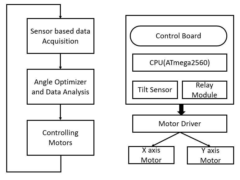
In this section, we describe the overview of the wheelchair balancing system thoroughly. Put another way, our proposed system can successfully balance the wheelchair seat for four directions of the wheelchair (left, back, front and right) in any kind of terrain. As a result, the seat is able to be in horizontal. Furthermore, the system periodically estimates the tilt angle of the seat to maintain its balance state.
Figure 1 show how the sensor angle value is obtained in real time, which is based on operation behavior of X-axis and Y-axis motors. However, due to system nature, the motor does not have adjustable speed, so the motor cannot support turn right or turn left.
We use a new hybrid PWM [6] as a voltage control method for the following case. That is, we design a process which sends the current output of a speed controller to the current of a controller. This design assists us to control the voltage of a motor. Furthermore, we employ hysteresis techniques [7, 8] which are fast and simple with a high response rate. However, it has disadvantages such as its weightlifting and breadth of switching frequency in changing wheelchair seats. This drawback reduces the risks control of a wheelchair. Despite the obstacles, the techniques can maintain the switching frequency compared to PWM techniques. In consequence, we control a wheelchair motor conventionally by using the On/Off expression. More specifically, we increase or decrease the motor speed based on a wheelchair state such as increasing the speed when climbing up the hill.
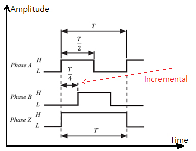
In this research, we apply two methods to control a motor, which are BLDC and PWM. These two techniques assist to avoid the error operations of the motor. Regarding motor controlling, we should aware of the motor position logically by employing an encoder to identify the motor position. In detail, we use Totem Pole outputs of optical encoders to detect motor position. In fact, optical encoders are a low-cost solution with a high number of PPR (Pulses Per Revolution) as well as its wide application. Besides, it also has the same split spacing in a moving board [18]. Besides, we implement three pulses to distinguish three slits. Furthermore, we set up the wheelchair system so that the light signal is expressed as LED as well as transform a physical signal to an electrical signal using phototransistor. Fig. 2 describes the illustration value used by the incremental encoder [9, 10] along with the cycle of pulse.
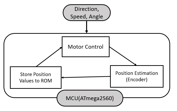
As shown in Fig. 6, if pulse A and B are at regular intervals, the angle output of the motor is about T=360°. Besides, pulse A is at the highest state if the output is T=90°. Consequently, we can determine A is at the lowest state if the output of the pulse B is at T=90°. As a result, we can detect a motor in the forward direction. Furthermore, we can deduct the rotation potion of the pulse Z the when total power block value is not valid. To avoid this error, we apply the ROM portion of ATmega or use an SD card to store values in a real-time manner, which are shown in Fig. 3.
MCU, which is ATmega2560, is the heart of speed control. Specifically, we have three inputs which are direction, speed, and angle of a motor. These values are passed to an encoder to estimate and calculate the moving state of the motor. Subsequently, we store position values in an internal memory such as ROM. In consequence, we can control the motor freely and smartly. Also, we can detect abnormal behavior of the motor and prepare backup solutions in advance.
3-3 Balancing Wheelchair Using Sensors
In this paper, we balance a wheelchair by employing two sensors which are Gyroscope and Tilt sensor. In detail, we obtain measure values every 1ms from a Tilt sensor when the sensor is in the propagation angle. In fact, tilt sensor can measure the angle state of a wheelchair. Furthermore, the tilt sensor can have an error measurement when the wheelchair is in the moving state and stop suddenly. To overcome this error, we apply the laws of inertia. However, the wheelchair could be halted because of the law of inertia. Consequently, we could mistakenly get the wrong angle values from the tilt sensor. Hence, we use an additional sensor which is Gyroscope sensor to avoid this mistake.
As mentioned above, we employ a Gyroscope sensor to overcome the problem of the acceleration of inertia. As expressed in Equation (1), the voltage of Gyroscope sensor is sensitive to angular values of the sensor as well as velocity. More specifically, it changes one angular unit (either minus or plus) of the sensor.
| (1) |
For example, we use a motor which is ATmega2560. It has resolution power value is about 1024. Besides, we use 3.3V Gyroscope sensor as well as its 2mV sensitivity. Substituting the above values in Equation (1), we achieve result shown in Equation (2) as the following:.
| (2) |
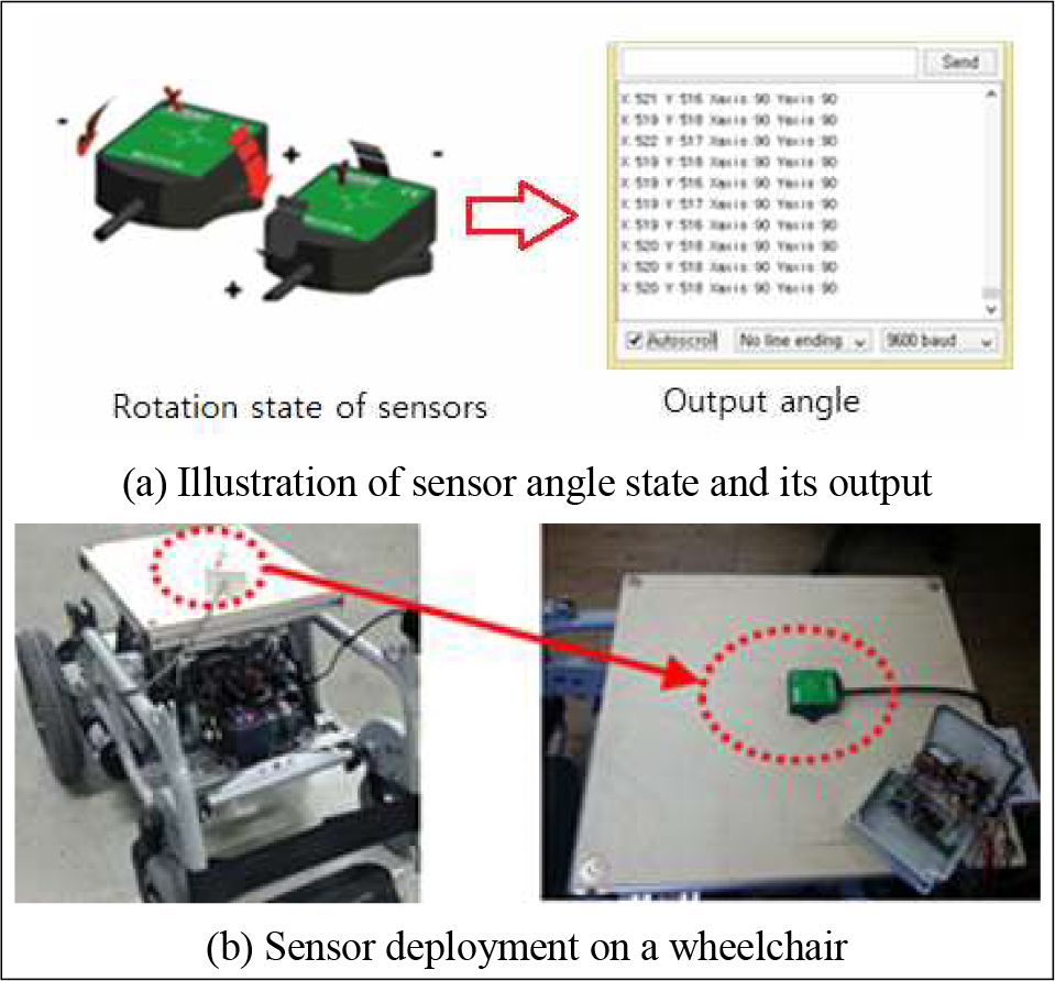
We estimate the angular value of the sensor each time when the wheelchair stop moving. Besides, we can also obtain the acceleration on the Gyroscope sensor, which is created by the movement of the wheelchair. Furthermore, the measurement assists us to avoid errors which occur in while controlling the wheelchair. In addition, we find some relations between sensors and the wheelchair. First, we can measure the moment acceleration of the wheelchair if the acceleration is less then equal to 1°. Secondly, we can estimate the current angle of the wheelchair from the tilt sensor if its acceleration is less than one degree. After estimating the angle of the wheelchair as shown in Fig. 4, Tilt and Gyroscope sensor can stably keep its balance state in order to reduce error measure.
Ⅳ. Balance Wheelchair Employing ZigBee
As addressed above, Tilt and Gyroscope sensor are stable with low or very low battery consumption. These sensors are crucial component of a balancing system. In this section, we describe a new module in our balancing system, which are Zigbee sensor. This sensor is used as a replacement for tilt sensor to estimate angle values. In fact, XBee (or so-called Zigbee) [11-14] module is wide application. It has frequency band about 2.4GHz. Besides, its data rate (RF) is about 250 Kbps ranging from 30m to 1.6 Km depending on each Zigbee model.
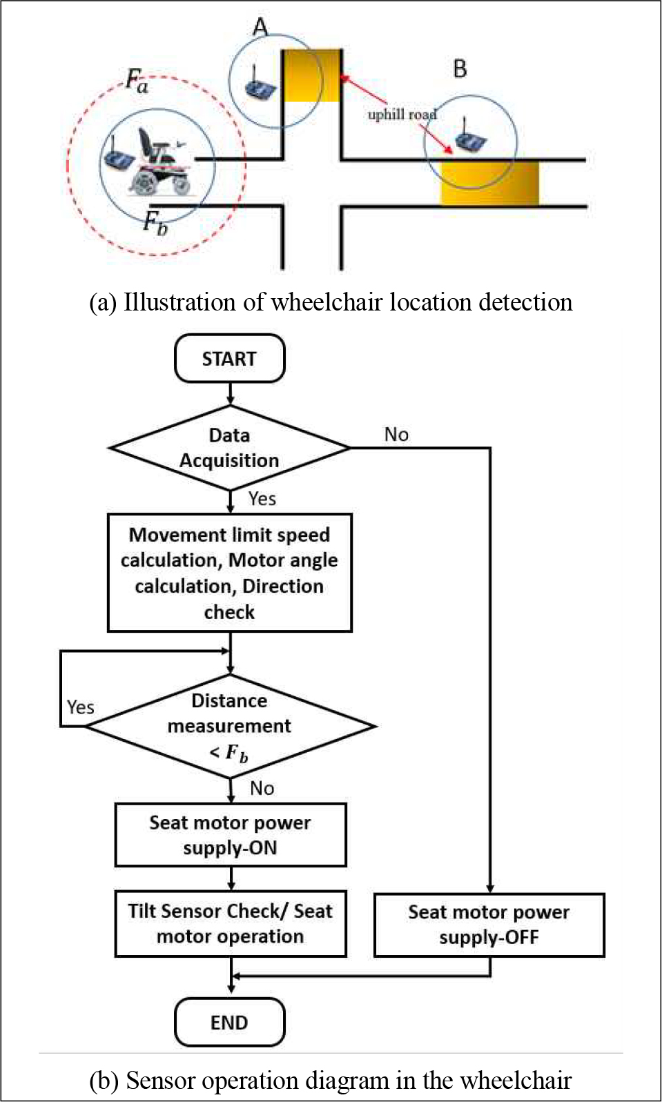
In this research, we apply XBee modules which have a maximum range (1.6Km) and set up in the wheelchair. We use a battery in the wheelchair so that we need to decrease the power consumption caused by any electric modules aiming to support the movement of the wheelchair. Besides, we use another XBee module which has maximum 100m range. We use this module to recognize terrain where the wheelchair is moving on. In detail, Fig. 5(a) illustrates the communication between the wheelchair and XBee sensors while moving. This communication supports the wheelchair to locate ramps on street. More specifically, The sensors which are set up in the wheelchair communicates with two XBees locating in area B and A respectively. Data from these XBees can be transferred by employing the communication channel. Besides, the channel can assist the wheelchair to estimate the distance between the wheelchair and the XBee modules. Furthermore, Fig. 5(b) shows a diagram representing the behavior of sensors installing in the wheelchair. If the wheelchair cannot detect signal from any XBee, we will cut off the power supply for the balancing module. In contrast, if it can connect and obtain data from an XBee module, it analyzes and estimates the limit of wheelchair movement speed as well as checking the motor angle and its direction. Besides, it also can measure the distance between the wheelchair and XBee modules.
| (3) |
Fig 5(b) - ② shows that if the measured distance is higher than current distance, we will cut of the power supply for the motor module. In addition, we employ the tilt sensor when the distance is short to assist the wheelchair to go up the hill without any trouble. If the measured distance is longer than the XBee range, it states the wheelchair is backed to ground. Subsequently, we shut off the power supply for the wheelchair balancing module.
We employ Equation (3) to estimate the distance between two XBee modules and the wheelchair based on the signal of a communication channel. In the Equation, 17.32 is a constant to calculate the radius between two XBee. fghz is the frequency of the XBee. dkm, dmax are the minimum and maximum transmitting distance.
Ⅴ. Experiments and Results
5-1 Experiment on Battery Power
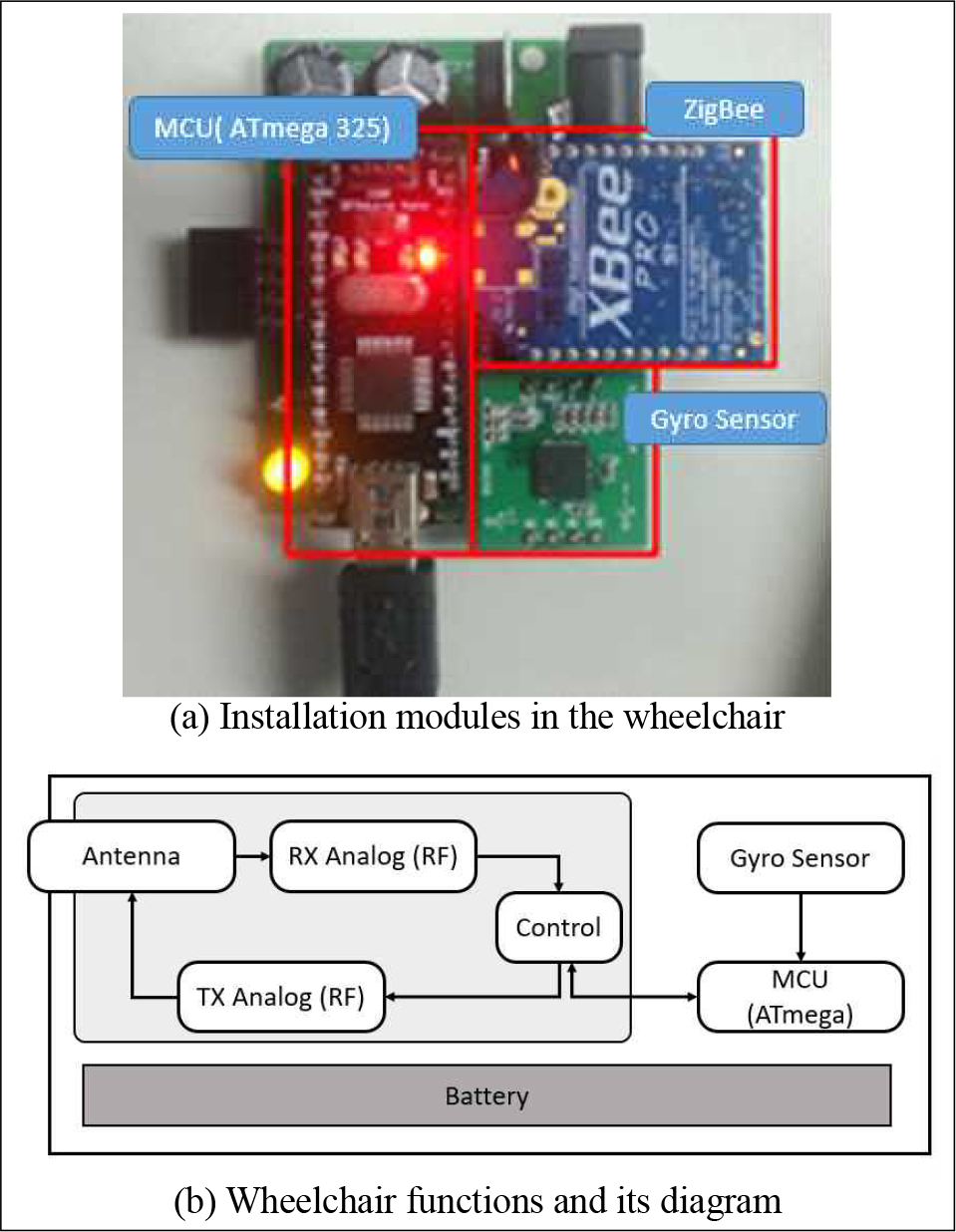
Figure 6 demonstrates the XBee modules which are employed to detect hills and obstacles. Fig. 6(a) is the real installation of the module, and Fig. 6(b) is a function diagram. In the system, we use Xbee to control MCU. Besides, we use the tilt sensor to estimate a terrain slope every 500 milliseconds. More detail, we first obtain tilt value of the sensor and use Equation (1) to measure distance. Furthermore, we use other wire sensors which are directly connected to the wheelchair without any wireless channel to reduce battery consumption.
We use Equation (4) to calculate battery power consumption which is used for the wheelchair XBee. In the equation, Pc is battery power consumption (mAh), Bc is battery capacity (mAh), and Ecurr is the current of RX or TX (mA). In the experiment, we use a battery which has capacity of about 2000 mAh to evaluate our proposed system in Fig. 6.
| (4) |
5-2 Evaluating the Sensor in the Balancing System
In order to prove the effect of sensor in balance system, we conducted experiments with Gyro sensor and without Gyro sensor. Tab. 1 represents the angle measurement which is obtained from the sensor in two cases as mentioned above, in which the cold color indicate for not apply Gyroscope sensor and hot color is for apply the sensor case. From the figure, we can conclude that if we apply Gyroscope sensors, the value of tilt sensor remains constant. Consequently, we can avoid any error occurred while the wheelchair is moving. Tab. 2 illustrates the experiment result of tilt sensor values with and without using the Gyroscope sensor while moving uphill.
Tab. 2 shows the angle value of tilt sensor when the wheelchair go uphill 10°. If we apply a Gyroscope sensor, wheelchair angle is always stable without any changes. In oppose, if we do not apply the sensor, the wheelchair seat angle keep changing its state from high to low. Especially, the unstable state could lead to flipping the wheelchair. In consequence, we can determine that the wheelchair balancing system is crucial in the balancing system. It does not only provide a convenience ride but also assist us users safely.
Ⅵ. Conclusion
This paper studies an application of smart sensors in electric wheelchair seat balancing control system. First, we address the problem when the wheelchair goes uphill. Secondly, we introduce an enhancement of seat balancing. In order to balance the wheelchair seat in real-time, we apply BLDC motor. This motor assists us to estimate the position of encoder and movement state of the wheelchair accordingly. As a result, the use of Gyroscope Sensor ensures the balance and stability of the wheelchair. Furthermore, by using the Gyroscope sensor and Tilt sensor, the wheelchair can go safer and more reliable on the uphill terrain. In the future, variety type of sensor can be put into trial and comparison so the wheelchair could be better adapted to many landscape scenarios.
Acknowledgments
This work (Grants No. C0540574) was supported by Business for Cooperative R&D between Industry, Academy, and Research Institute funded Korea Small and Medium Business Administration in 2017. Furthermore, this research was supported by the MSIT(Ministry of Science and ICT), Korea, under the ITRC(Information Technology Research Center) support program(IITP-2018-2016-0-00314) supervised by the IITP(Institute for Information & communications Technology Promotion).
References
-
Baig, Mirza Mansoor and GholamHosseini, Hamid and Connolly, Martin J., “Mobile healthcare applications: system design review, critical issues and challenges,” Australasian physical & engineering sciences in medicine, 38(1), pp. 23-38, 2015.
[https://doi.org/10.1007/s13246-014-0315-4]

-
Majumder, Sumit, Tapas Mondal, and M. Jamal Deen. “Wearable sensors for remote health monitoring,” Sensors, pp. 130, 2017.
[https://doi.org/10.3390/s17010130]

- Ilarri, Sergio, Thierry Delot, and Raquel Trillo-Lado. “A data management perspective on vehicular networks,” IEEE Communications Surveys & Tutorials, pp. 2420-2460.
-
Guzman, Hugo, Mario J. Duran, Federico Barrero, Blas Bogado, L. Sergio, and Toral Marín, “Speed Control of Five-Phase Induction Motors With Integrated Open-Phase Fault Operation Using Model-Based Predictive Current Control Techniques,” IEEE Trans. Industrial Electronics 61, no. 9 (2014): pp. 4474-4484.
[https://doi.org/10.1109/TIE.2013.2289882]

- Yanamshetti, Raju, and Juhi Nishat Ansari. “Microcontroller Controlled BLDC Drive for Electric Vehicle,” International Journal of Engineering 1, no. 10 (2012).
- Varun, M., Kapil Shukla, Ramkrishan Maheshwari, and Amit Kumar Jain, “A new hybrid PWM for two parallel connected interleaved two-level inverter to reduce output current ripple,” In Power and Energy Systems (ICPES), 2017 IEEE 7th International Conference on, pp. 74-79, 2017.
- Bakan, A. Faruk, and A. Talha Dudak, “Implementation of digital adaptive hysteresis current control technique,” In Electrical and Electronics Engineering (ELECO), 2017 10th International Conference on, pp. 416-422, 2017.
-
Fereidouni, Alireza, Mohammad AS Masoum, and Keyue M. Smedley, “Supervisory nearly constant frequency hysteresis current control for active power filter applications in stationary reference frame,” IEEE Power and Energy Technology Systems Journal Vol. 3, No. 1, pp. 1-12, 2016.
[https://doi.org/10.1109/JPETS.2015.2501423]

- Anuchin, Alecksey, Valentina Astakhova, Dmitry Shpak, Alexandr Zharkov, and Fernando Briz, “Optimized method for speed estimation using incremental encoder,” In Power Electronics (Ee), 2017 International Symposium, pp. 1-5, 2017.
- Chen, Yangyang, Ming Yang, Jiang Long, Dianguo Xu, and Frede Blaabjerg, “M/T method based incremental encoder velocity measurement error analysis and self-adaptive error elimination algorithm,” In Industrial Electronics Society, IECON 2017-43rd Annual Conference of the IEEE, pp. 2085-2090, 2017.
-
Lee, Jun Kyu, Hong Min Seung, Chung Il Park, Joo Kyung Lee, Do Hyeong Lim, and Yoon Young Kim. “Magnetostrictive patch sensor system for battery-less real-time measurement of torsional vibrations of rotating shafts,” Journal of Sound and Vibration Vol. 414, pp. 245-258, 2018.
[https://doi.org/10.1016/j.jsv.2017.11.023]

-
Shue, Sam, Lauren E. Johnson, and James M. Conrad, “Utilization of XBee ZigBee modules and MATLAB for RSSI localization applications,” In Southeast Conference, pp. 1-6, 2017.
[https://doi.org/10.1109/SECON.2017.7925305]

- Bhat, Sohaib, Nishant Kaul, Anchal Gupta, and Ved Prakash, “XBee based novel wireless technique to simplify locomotion of physically handicapped persons,” In Engineering and Systems (SCES), IEEE Students Conference on, pp. 1-5, 2015.
- Karyemsetty, Nagarjuna, Badugu Samatha, and K. Himantha Rao, “Design and deployment of Vehicle Tracking System in VANETs using Xbee Pro: Prototype model,” In Communication Networks (ICCN), 2015 International Conference on, pp. 97-100, 2015.

2013 : Hanoi University of Science and Technology, Vietnam (B.S. Degree).
2013~2015: Researcher and Developer at Samsung Vietnam Mobile R&D Center – SVMC.
2015~now: School of Electronics and Computer Engineering - Smart & Media Computing Laboratory.
※Research Interests : Mobile Cloud Computing, Next Generation of Mobile Platform, Mobile Operating System and Peer-to-Peer Network

2013 ~ Now : Chonnam National Univeristy (B.S. Degree).
※Research Interests : Mobile Cloud Computing, Next Generation of Mobile Platform
2001 : University of Utah, Salt Lake City, Utah, USA (B.S. Degree).
2005 : Korea Advanced Institute of Science and Technology (KAIST) (M.S Degree).
2008 : Korea Advanced Institute of Science and Technology (KAIST) (Ph.D Degree).
2005~2008: Researcher in IPTV Infrastructure Technology Research Laboratory, Broadcasting/Telecommunications Convergence Research Division, Electronics and Telecommunications Research Institute (ETRI).
2009~2011: Professor in Korea Nazarene University, Chon-an, Korea.
2011~now: Professor in Chonnam National University, Gwangju, Korea.
※Research Interests : QoS/QoE, Measurement/ Management, IPTV, Mobile IPTV, Smart TV, Multimedia Communication and Digital Media Arts.
